How Air Source Heat Pumps Work: A Complete Guide with Diagrams
As the demand for energy-efficient heating solutions grows, air source heat pumps have become a leading choice for homeowners and businesses. These systems provide sustainable heating and cooling by harnessing renewable energy sources, reducing reliance on fossil fuels.
Understanding how air source heat pumps operate is key to making informed decisions. This guide breaks down the air source heat pump diagram, explaining each component—including the compressor, condenser, expansion valve, and evaporator—to show how heat is transferred and utilised. Whether you're considering an installation or exploring heat pump training courses, this article provides a clear and comprehensive overview.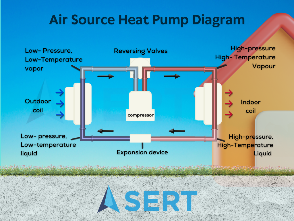
Breaking Down the Air Source Heat Pump Diagram
1. Compressor: The Heart of the System
At the core of the air source heat pump lies the compressor. This component plays a pivotal role in the refrigeration cycle by pressurising the refrigerant gas, elevating its temperature and pressure. As the refrigerant passes through the compressor, its molecules become tightly packed together, generating heat energy.
2. Condenser: Transforming Gas into Liquid
Moving along the cycle, the high-pressure, high-temperature refrigerant gas flows into the condenser. Here, it undergoes a crucial transformation: from gas to liquid. Through the process of condensation, heat is released into the surrounding environment, allowing the refrigerant to shed its excess heat and convert into a liquid state.
3. Expansion Valve: Regulating Refrigerant Flow
The next stop in our journey through the air source heat pump diagram is the expansion valve. This component serves as a throttle, controlling the flow of liquid refrigerant into the evaporator. By reducing the pressure of the refrigerant, the expansion valve sets the stage for the next phase of the cycle.
4. Evaporator: Absorbing Heat from the Surroundings
As the liquid refrigerant enters the evaporator, it encounters a low-pressure environment. This triggers evaporation, causing the refrigerant to absorb heat from the surrounding air. In the process, the air source heat pump extracts thermal energy from the external environment, effectively heating or cooling the indoor space as desired.
Understanding the Refrigeration Cycle: A Sustainable Solution
The air source heat pump diagram provides a visual roadmap of the refrigeration cycle, illustrating how thermal energy is transferred and manipulated to achieve desired heating or cooling effects. Unlike traditional heating systems reliant on fossil fuels, air source heat pumps harness renewable energy sources, making them an eco-friendly choice for modern heating and cooling needs.
Embracing Innovation in Heating Technology
As we conclude our exploration of the air source heat pump diagram, it becomes evident that these systems represent a paradigm shift in heating technology. By leveraging the principles of thermodynamics and refrigeration, air source heat pumps offer a sustainable alternative to conventional heating methods, paving the way for a greener, more energy-efficient future.
Understanding the mechanics behind air source heat pumps not only empowers consumers to make informed decisions but also highlights the potential of innovative technologies to drive positive change in the fight against climate change. With SERT's comprehensive training courses in air source heat pumps, individuals can equip themselves with the knowledge and skills to contribute to this transformative journey towards a more sustainable world.